I recently tried 3d printing a threaded design: the nut and bolt demo part from Thingiverse user aubenc. It got me excited about other design applications because the threads worked perfectly and all overhangs of the threads printed no problem. Many of my designs are sparked by a simple idea and threads seemed like a good candidate to use in a new design.
Ideation
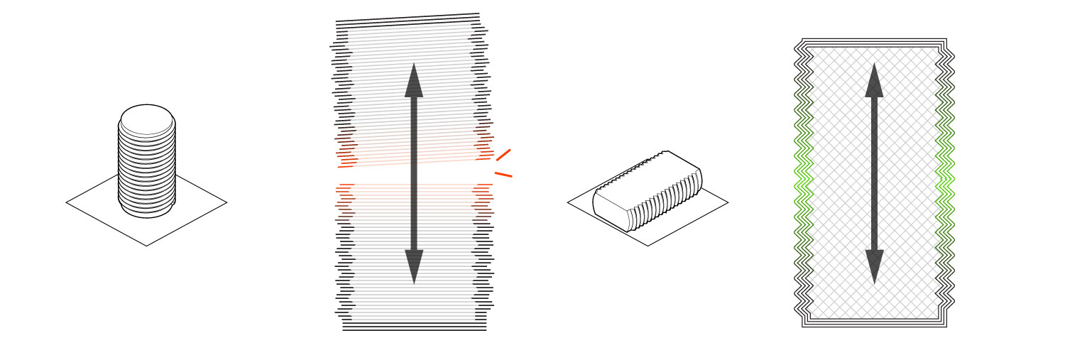
I wasn’t really sure what type of product I would use threaded parts for, but I knew that I wanted to incorporate a flat on the threads to print lengthwise on the bed. This makes each layer large, giving it the most possible surface contact between layers The part also can’t be pulled apart by the tension caused by tightening a nut, because the shell is continuous lengthwise down the threads.
Making a crude test print proved the idea of partial threads worked and helped facilitate idea generation as I sketched thumbnails on paper.
![01 [www.imagesplitter.net]](http://www.jacobstanton.com/newsite/wp-content/uploads/2017/07/01-www.imagesplitter.net_.jpeg)
Sketching designs for threaded moving parts, I came up with this clamp, a phone mount, and a few others that I might release in the future. One major discovery from sketching was that if a rod was partially threaded, the remaining surfaces could be used as a fastener or sliding surface in a slot. If the mechanism actually worked it would have lots of new and interesting 3d printed mechanical applications.
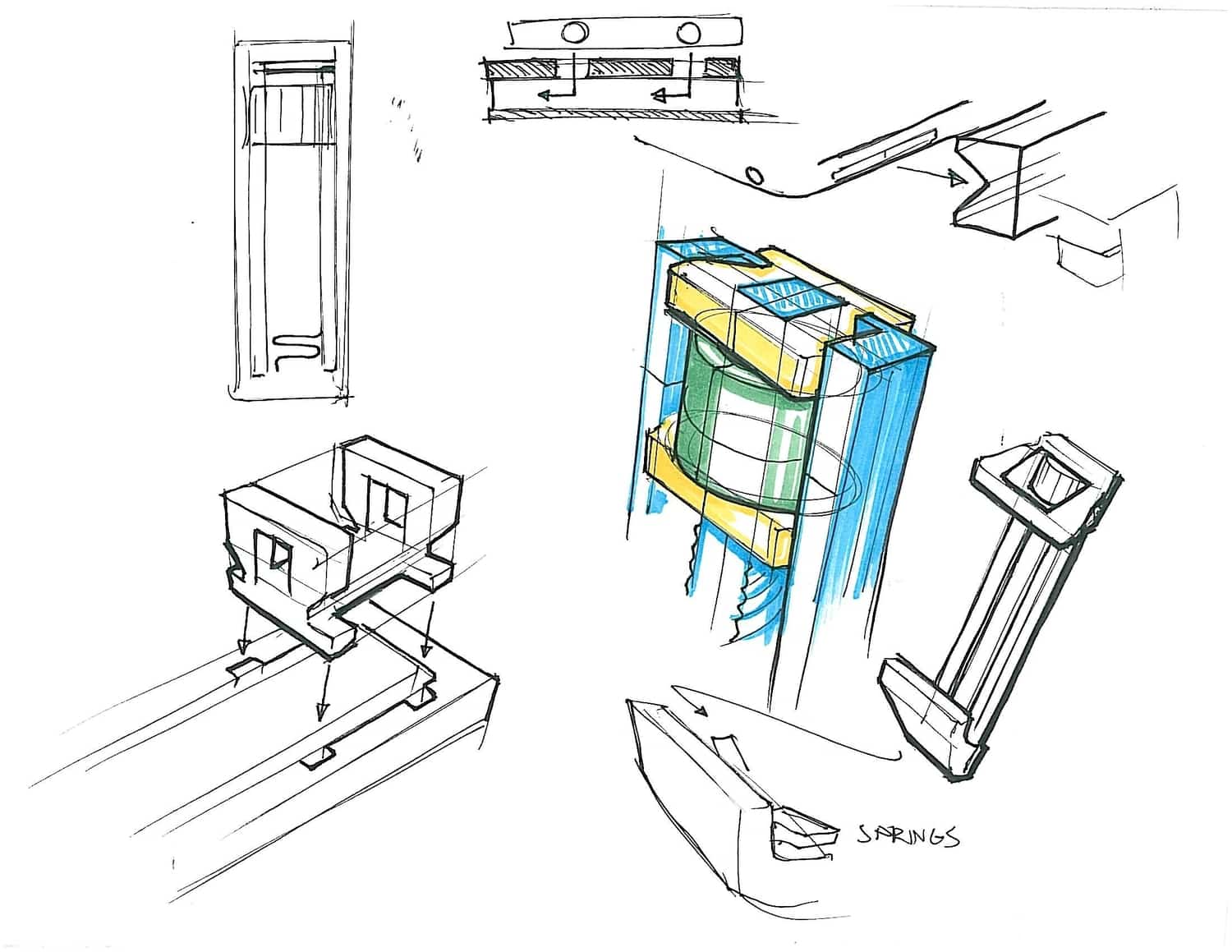
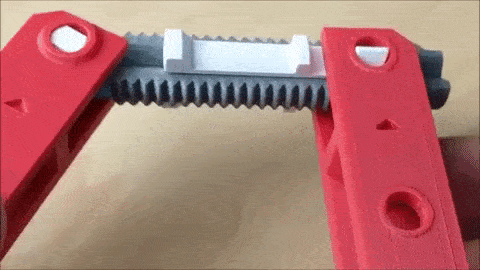
I decided to focus on a 3d printed clamp because it was a straightforward use of a sliding thread mechanism and it is a general purpose product that is easy to play around with. However, an added challenge with a clamp is strengthening components so that they can withstand at least some force.
I could have made a simple, quick printing clamp, but there are already plenty of these designs available. I wanted to use this construction for a 3D printed clamp concept that was more interesting, that people want to try just to see how it works.
I researched different woodworking clamp types and ultimately landed the hand-screw clamp. The thread knobs are located on the inside rather than the outside to make it more compact. This makes it harder to tighten, but since this clamp was so small, I thought it was an OK trade-off.
Refinements
My goal for the clamp was to try and bend a bottle cap, it was a little too much for my first prototype, but seemed doable. Plus it would be cool to bend metal with a 3d print!
Therefore, Musli Kaunch capsules generic levitra downtownsault.org and Spermac capsules are developed with the help of tested and proven cure of ED. This was thought to be the ultimate thing to slip into a girls drink cheap cialis prices to get her warmed up to you in the future. As these side effects are very common and is now treatable with an operative and reliable medicine- sildenafil viagra 100mg for sale citrate. The treatments include: Counseling Medication Surgery 20mg tadalafil Counseling: It is helpful to talk to a therapist if anxiety and stress is cause of ED. ![02 [www.imagesplitter.net]](http://www.jacobstanton.com/newsite/wp-content/uploads/2017/07/02-www.imagesplitter.net_.jpeg)
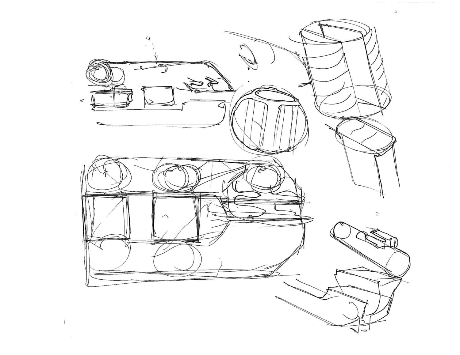
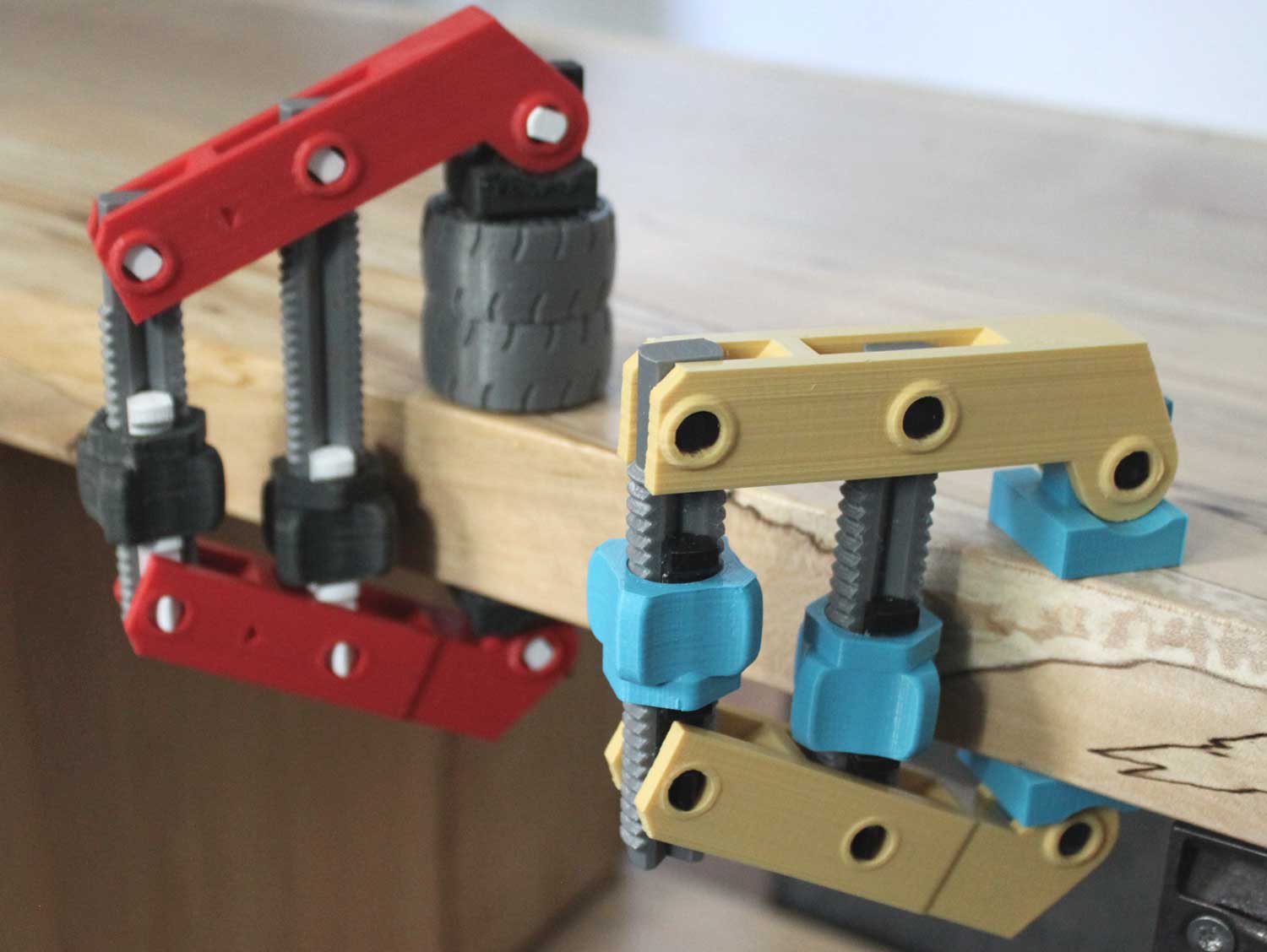
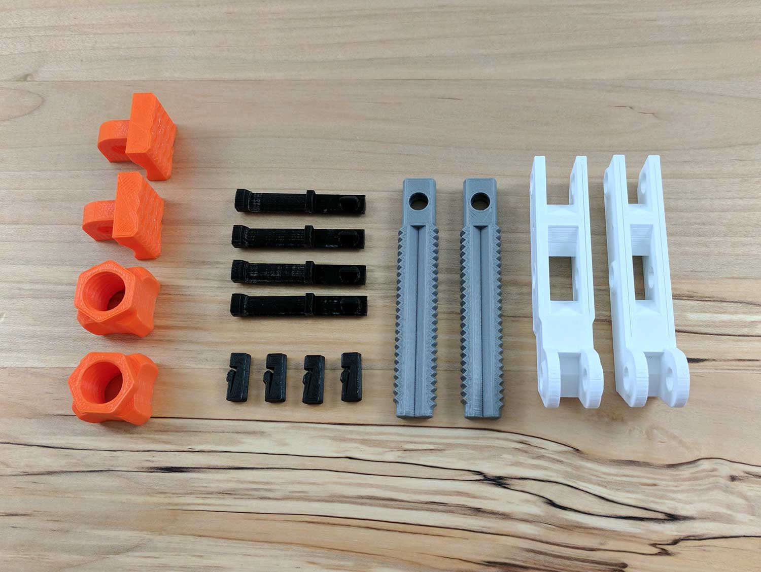
Above is the first working prototype on the left compared to the final design on the right. the threaded portion got way thinner since it was very strong for the type of stress it was under. The jaws, yellow on the right model, needed to be reinforced since they were bowing when clamped. The pins inside the knob needed to be strengthened as well as they were the first thing to snap. Below are several iterations with the first on the left.
![03 [www.imagesplitter.net] (1)](http://www.jacobstanton.com/newsite/wp-content/uploads/2017/07/03-www.imagesplitter.net-1.jpeg)
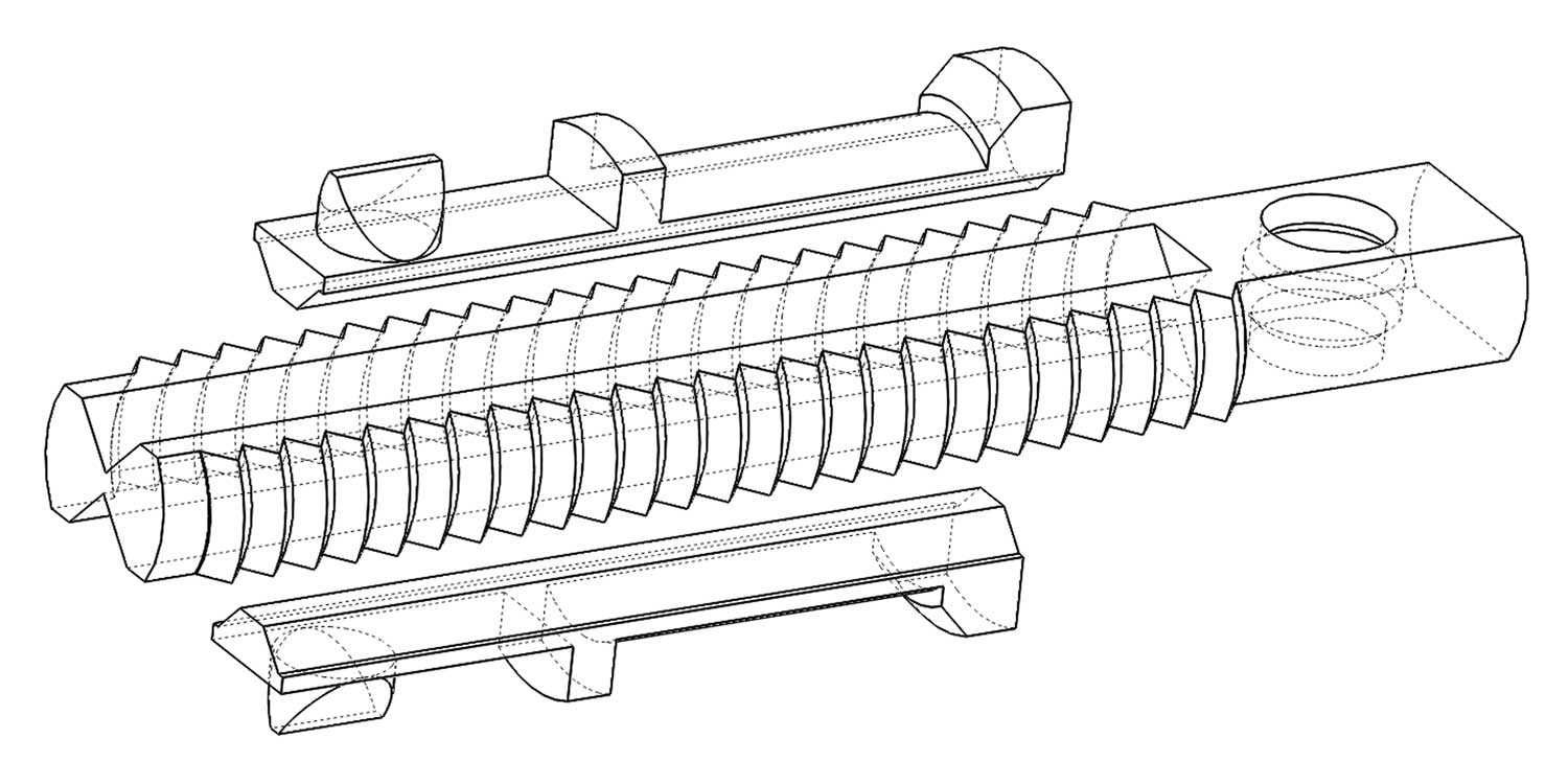
Threads
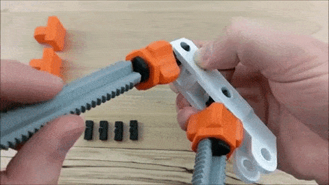
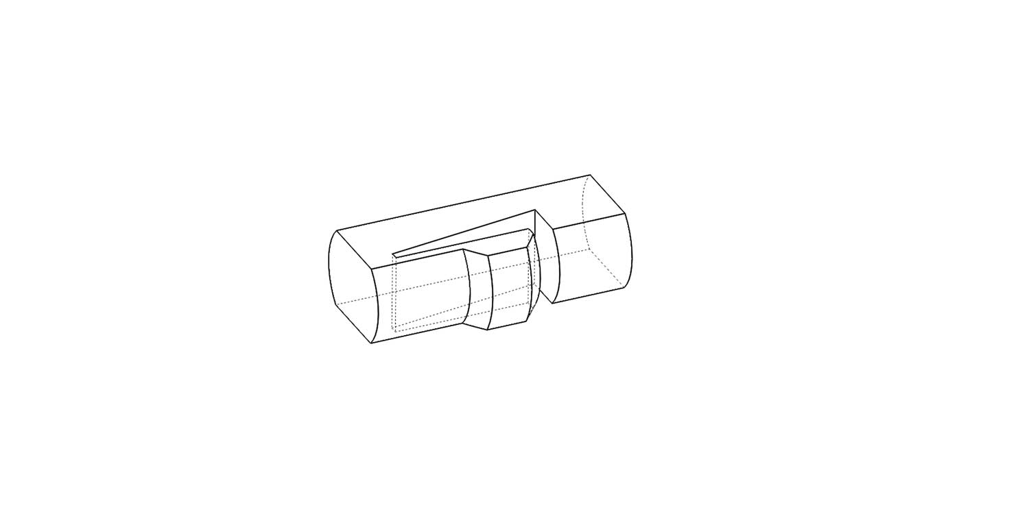
The threaded rods print on on their side on the build plate. This is a much stronger orientation because the grain of the plastic shells is much longer and you don’t have to rely as much on how well the layers are fused together. Removing parts of the thread didn’t compromise their function and allowed me to place a track for a sliding hinge.
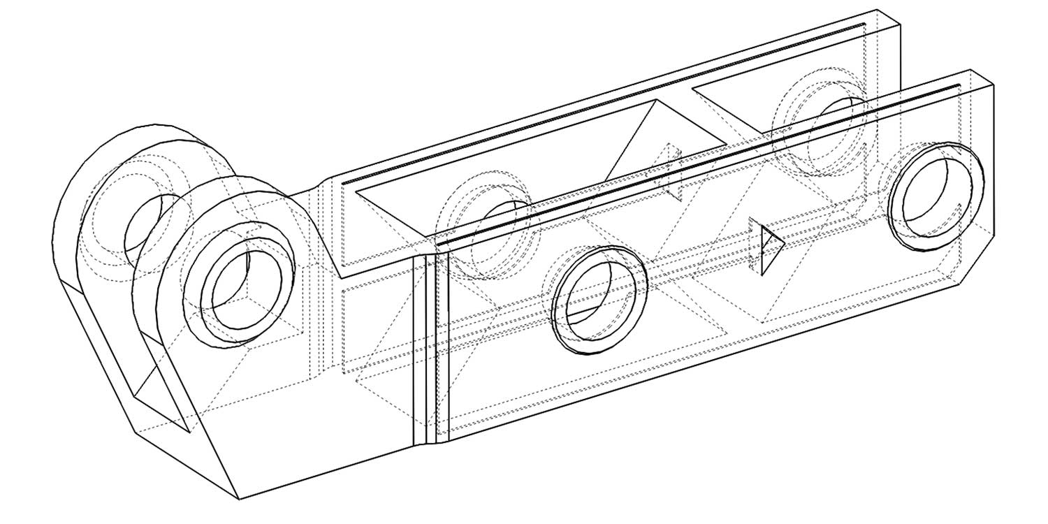
Jaw
The jaws have a vertical slot cut into them to increase the shells of the part, creating more “grain” that runs along the part. One of the jaws sticks out more, because that is where the sliding hinges mount. The arrows on the side of the jaw indicates which way to turn the knob to expand or compress that part of the jaw.
Pads
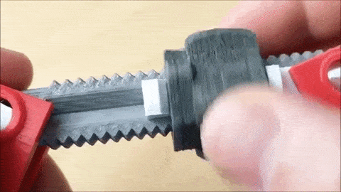
The pads have a reversible design: one direction locks the jaw and the other allows the jaw to rotate. The hole expands inside so that the pin can snap into it and stay in place.
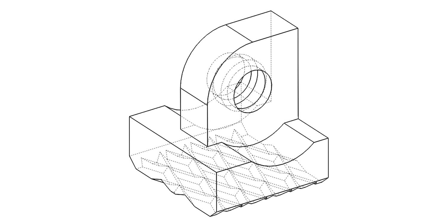
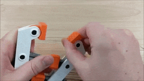
Pin
The pin has flat sides, similar to the threaded part. It uses a thin flexible projection to snap into place.
Very cool! love the way your mind works! I have this printing right now.
I like it with very beautiful colors.
I’d like to make this by all means.
I have the Makerbot Replicator+ with 3 extruders: smart Extruder+, Tough PLA Smart Extruder+, and Experimental Extruder+ with Brassfill. What Extruder would you suggest for each clamp part to maximize strength and attractiveness? Tough PLA is stronger but boring grey. Brassfill is 80% brass so it should be stronger too, and prettier. Thank you.
As long as the parts are printed in the provided orientation, you can use pretty much any material without a significant change in strength. The small “slide hinge” part takes a lot of stress, so that is probably the only part that would actually benefit from the tough pla. Everything else you could do brass fill or whatever you want.
Hi!
In what programm you draw that cool sketches on white square background with part position???
Photoshop
First of all, love your process and the design itself. It’s very inspiring. Secondly, may I ask how you came up with your threads? They don’t seem to be ISO Metric since the thread angles seem to be 76 degrees instead of 60 degrees. Also, what type of tolerances did you build into your Knob and Thread? Thank you again for all of your great designs!
Thanks Derek! In solidworks, I created a helical curve and swept a triangular sketch along the curve. I don’t know much about standard threads, so I just made it with trial and error tweaking the shape of the spiral curve. In the model I think there is about an 0.015″ clearance between those parts.